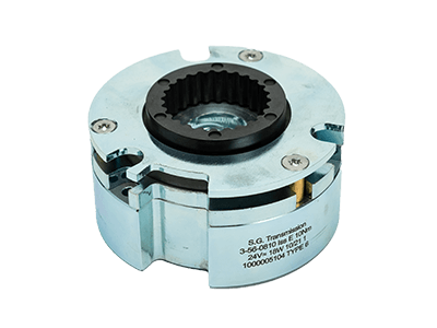
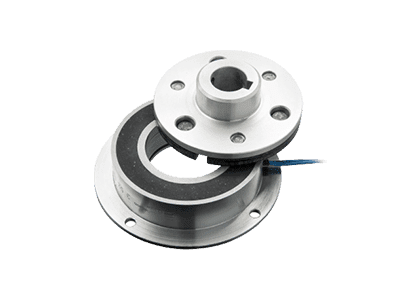
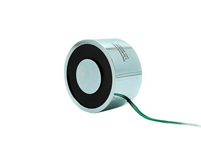
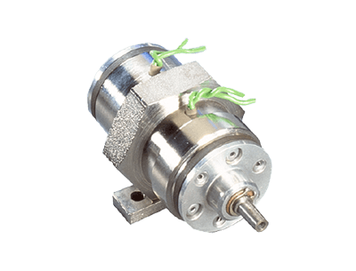
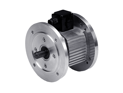
Permanent magnet power off brake
Fail-safe, zero backlash permanent magnet power off brakes for use in high precision, high power applications.
Enquire NowKey features
- Fail-safe
- Zero backlash
- High power density
- Closed-circuit principle (active when de-energized)
- Precise holding
- Low moment of inertia
- Optional installation position
Product description
Permanent magnet power off brakes from SG Transmission offer high power density, accuracy and durability within a compact module. Available as a standard option, customised to suit a specific installation position or designed as a completely bespoke solution, our permanent magnet brakes are manufactured with performance at the forefront.
Permanent magnet power off brakes work according to the closed-circuit principle, designed so that when the power is off, the brake is engaged (power-off brake engagement). The permanent magnet brake is available in the same mounting style as a conventional power on brake with flange or spigot mounting options therefore it is easier to incorporate in to existing designs
Permanent magnet brakes are ideal for use in robotics, medical technology and servomotor applications due to their simple structure, performance to size ratio and abrasion resistance.
Fail-safe
As the braking effect is generated in the de-energized state, the permanent magnet brake can be used in fail-safe applications to automatically stop the drive when electrical power fails. It also offers energy saving benefits where long holding or downtimes are required due to its ability to retain hold without voltage being applied.
Zero backlash
The permanent magnet power off brake is essentially zero backlash creating an increased level of safety and accuracy. Unlike conventional fail-safe (spring-loaded) brakes, which have a linear movement due to the spring behaviour, permanent magnet brakes may be considered as ‘torsionally rigid’ where linear movement is achieved via deformation of a diaphragm spring, not the clearance between rotating parts.
Operating temperature
It is important that the operating temperature for both permanent magnet and spring-loaded brakes are considered in advance. When voltage/current is applied, the brakes will disengage and heat will be generated by the coil. This heat changes the coil resistance and causes a shift in the release voltage/current. Therefore, the SG Transmission permanent magnet brake is tested at an ambient temperature of 20°C when hot to optimise the disengagement window.
Get in touch with our engineers to discuss your requirements.
Multi-pole
The multi-pole version of the permanent magnet brake provides a solution to give increased torque within the same size casing. The improved performance is achieved by doubling the number of working magnetic poles and this technology can also be applied to clutches and power-on brakes.
Rare earth magnets
At SG Transmission, we use rare earth magnets to create a higher flux density (tesla/gauss) than comparable, older design ferrite magnets. This allows the highest possible torque range to be achieved within the smallest possible dimensions.
Armature and fixing options
Our permanent magnet brakes are available for installation by either direct fastening holes in the magnet body, or with a base plate. This installation position can be freely selected during the design stage.
In addition, our design engineers can create customised armature styles depending on the application but as standard are supplied with C.L., C.C. and C.R. armature types and feature bores and keys to suit specific requirements.
To download our standard product line datasheet, see relevant downloads.
For custom and application specific designs, click here to speak with our engineers.
Key features
- Fail-safe
- Zero backlash
- High power density
- Closed-circuit principle (active when de-energized)
- Precise holding
- Low moment of inertia
- Optional installation position
Product description
Permanent magnet power off brakes from SG Transmission offer high power density, accuracy and durability within a compact module. Available as a standard option, customised to suit a specific installation position or designed as a completely bespoke solution, our permanent magnet brakes are manufactured with performance at the forefront.
Permanent magnet power off brakes work according to the closed-circuit principle, designed so that when the power is off, the brake is engaged (power-off brake engagement). The permanent magnet brake is available in the same mounting style as a conventional power on brake with flange or spigot mounting options therefore it is easier to incorporate in to existing designs
Permanent magnet brakes are ideal for use in robotics, medical technology and servomotor applications due to their simple structure, performance to size ratio and abrasion resistance.
Fail-safe
As the braking effect is generated in the de-energized state, the permanent magnet brake can be used in fail-safe applications to automatically stop the drive when electrical power fails. It also offers energy saving benefits where long holding or downtimes are required due to its ability to retain hold without voltage being applied.
Zero backlash
The permanent magnet power off brake is essentially zero backlash creating an increased level of safety and accuracy. Unlike conventional fail-safe (spring-loaded) brakes, which have a linear movement due to the spring behaviour, permanent magnet brakes may be considered as ‘torsionally rigid’ where linear movement is achieved via deformation of a diaphragm spring, not the clearance between rotating parts.
Operating temperature
It is important that the operating temperature for both permanent magnet and spring-loaded brakes are considered in advance. When voltage/current is applied, the brakes will disengage and heat will be generated by the coil. This heat changes the coil resistance and causes a shift in the release voltage/current. Therefore, the SG Transmission permanent magnet brake is tested at an ambient temperature of 20°C when hot to optimise the disengagement window.
Get in touch with our engineers to discuss your requirements.
Multi-pole
The multi-pole version of the permanent magnet brake provides a solution to give increased torque within the same size casing. The improved performance is achieved by doubling the number of working magnetic poles and this technology can also be applied to clutches and power-on brakes.
Rare earth magnets
At SG Transmission, we use rare earth magnets to create a higher flux density (tesla/gauss) than comparable, older design ferrite magnets. This allows the highest possible torque range to be achieved within the smallest possible dimensions.
Armature and fixing options
Our permanent magnet brakes are available for installation by either direct fastening holes in the magnet body, or with a base plate. This installation position can be freely selected during the design stage.
In addition, our design engineers can create customised armature styles depending on the application but as standard are supplied with C.L., C.C. and C.R. armature types and feature bores and keys to suit specific requirements.
To download our standard product line datasheet, see relevant downloads.
For custom and application specific designs, click here to speak with our engineers.
To download the technical drawings for this product fill in your details below and we will send you a link to the files.
"*" indicates required fields
Permanent magnet power off brake technical drawing
See related downloads for full datasheet
Download drawingsSee related downloads for full datasheet
| Size | Torque TS (Nm) | Max P20 (W) | A1 (H9) | A2 (H8) | A3 | A4 (AF) | C4 | E2 max (H7) | E4 (H8) | E5 | E8 | E9 | G | K | N1 | N2 | N5 | R | S1 | S4 | T | U1 | U2 | U7 | U11 | V | W1 | W4 |
|---|---|---|---|---|---|---|---|---|---|---|---|---|---|---|---|---|---|---|---|---|---|---|---|---|---|---|---|---|
| 03 | 0.4 | 6 | 38.5 | 28 | 28.5 | 30 | 7.8 | 8 | 9.2 | 17 | 9 | - | 0.15 | 4 | 33.5 | 19.5 | 22 | 16 | 10.5 | 2.7 | 1.5 | 2.6 | 2.15 | M3 | M2 | 1.6 | 5.3 | - |
| 04 | 1.25 | 8 | 62.5 | 40 | 40 | 45 | 14.2 | 8 | 13 | 16 | 13 | 12 | 0.15 | 6 | 54 | 29 | 32.5 | 21 | 17.5 | 3 | 3 | 3.5 | 3.2 | M3 | M2 | 1.5 | 12.2 | 5.3 |
| 05 | 2.5 | 12 | 75 | 53 | 56 | 56 | 17 | 15 | 24 | 24 | 24 | 23 | 0.20 | 6.5 | 61 | 46 | 48 | 20.8 | 20.5 | 3.4 | 3.3 | 4.5 | 3.1 | M5 | M3 | 1.5 | 13.5 | 7 |
| 06 | 9 | 20 | 80 | 63 | 63 | 66 | 15 | 17 | 35 | 27 | 32 | 27 | 0.20 | 6.5 | 72 | 46 | 49 | 26.6 | 19 | 4.1 | 3 | 4.5 | 3.1 | M5 | M4 | 1.5 | 11.5 | 7.5 |
| 07 | 5 | 20 | 90 | 70 | 73 | 70 | 20 | 20 | 30 | 30 | 32 | 30 | 0.25 | 8 | 79.5 | 60 | 61 | 25.3 | 24.2 | 4.2 | 3.5 | 5.5 | 4.1 | M5 | M3 | 1.5 | 15 | 9.2 |
| 09 | 12 | 18 | 115 | 85.5 | 90 | 90 | 25 | 30 | 40 | 40 | 43 | 40 | 0.25 | 10 | 102 | 76 | 75 | 26.6 | 30 | 5 | 3.5 | 6.5 | 5.1 | M5 | M3 | 2 | 20 | 10 |
| 11 | 30 | 22 | 132 | 110 | 110 | 110 | 30 | 35 | 50 | 49 | 52 | 49 | 0.30 | 13 | 121 | 95 | 90 | 33 | 36.2 | 6.2 | 3.75 | 6.5 | 6.1 | M6 | M4 | 4.7 | 24 | 12.2 |
| 12 | 60 | 28 | 150 | 126 | 126 | 128 | 30 | 40 | 62 | 57 | 62 | 49 | 0.40 | 12.5 | 137 | 95 | 106 | 37.8 | 37.2 | 7.1 | 5 | 6.6 | 6.1 | M6 | M6 | 3.2 | 20 | 13 |
See related downloads for full datasheet
| Size | Torque TS (Nm) | Max P20 (W) | A1 (H9) | A2 (H8) | A3 | A4 (AF) | C4 | E2 max (H7) | E4 (H8) | E5 | E8 | E9 | G | K | N1 | N2 | N5 | R | S1 | S4 | T | U1 | U2 | U7 | U11 | V | W11 |
|---|---|---|---|---|---|---|---|---|---|---|---|---|---|---|---|---|---|---|---|---|---|---|---|---|---|---|---|
| 4 | 22 | 8 | 62.5 | * | 40 | 45 | * | * | 15 | * | 13 | * | 0.15 | 6.5 | 54 | 29 | 32 | 23 | * | 5.05 | 2 | 3.5 | 3.2 | * | * | 1.5 | * |
| 6 | 12 | 20 | 88.9 | 66 | 67.7 | 66 | * | * | 35/34 | 27 | 35/34 | * | 0.2 | 8 | 79.4 | 46 | 56 | 27.6 | 18.5 | 3.9 | 3 | 4.5 | 3.1 | M5 | 3xM4 | 1.5 | 11.1 |
| 9 | 22 | 18 | 115 | * | 90 | 90 | * | * | 40 | * | 43 | * | 0.25 | 10 | 102 | 76 | * | 26.6 | * | 5 | 3.5 | 6.5 | 5.1 | * | * | 2 | * |
| 11 | 40 | 22 | * | 104 | 110 | * | 30 | 35 | 50 | 49 | 56 | 49 | 0.3 | 13 | * | 95 | 90 | 30.7 | * | 5.8 | 6 | * | 6.3 | * | 6xM4 | 2 | * |
| 16 | 120 | 40 | 190 | * | 160 | ROUND | * | * | 68 | * | 63 | * | 0.4 | 13 | 175 | 120 | * | 41.2 | * | 9.4 | 10 | 6X6.4 | 8.3 | * | * | 6 | * |
See related downloads for full datasheet
| Size | Torque TS (Nm) | Max P20 (W) | A1 (H9) | A2 (H8) | A3 | A4 (AF) | C4 | E2 | E4 (H8) | E5 | E8 | E9 | G | K | N1 | N2 | N5 | R | S1 | S4 | T | U1 | U2 | U7 | U11 | V | W1 | W4 |
|---|---|---|---|---|---|---|---|---|---|---|---|---|---|---|---|---|---|---|---|---|---|---|---|---|---|---|---|---|
| 08 | 18 | 24 | 100 | 80 | 80.2 | 80 | 20 | 22 | 35/42 | 38 | 38 | * | 0.25 | 8 | 90 | 60 | 63 | 29.9 | 24.7 | 4.7 | 3 | 5.5 | 4.1 | M5 | M4 | 1.5 | 16 | 8.7 |
| 09 | 22 | 18 | 115 | * | 90 | 90 | * | * | 40 | * | 43 | * | 0.25 | 10 | 102 | 76 | * | 26.7 | * | 5 | 3 | 6.5 | 5.2 | * | * | 2 | * | * |
| 10 | 35 | 22 | * | 100 | 100 | * | * | * | 52 | * | 52 | * | 0.3 | 10 | * | 78 | 76 | 37.5 | * | 5.8 | 5 | * | 5.1 | * | M5 | 2 | * | * |
| 11 | 40 | 24 | * | 104 | 109.6 | * | * | * | 56 | * | 58.5 | * | 0.3 | 12.8 | * | 95 | 90 | 30.7 | * | 5.8 | 6 | * | 6.4 | * | M4 | 4.7 | * | * |
